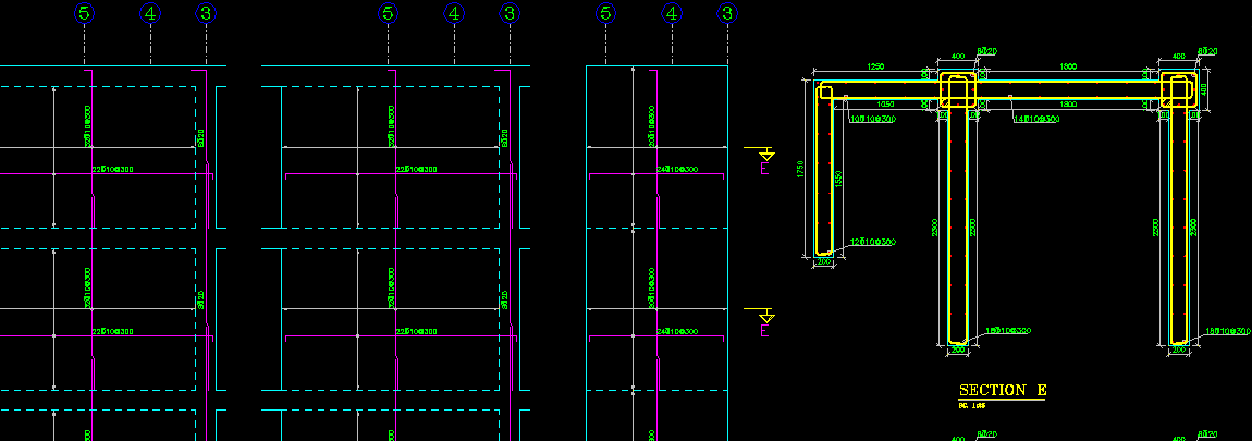
The main outputs of Omid Negar software are the details and drawings of concrete structure. For being more familiar with these outputs, the generated output drawings and details described in following. For viewing the output drawings and building the arranged ready to plot structural drawings, two window are used in program. These 2 windows are described in following.
A. Viewing Structural Details: Details Window
Selecting each detail for viewing and editing is done in Details window. The different types of details is described at the following:
1. Columns Plan of Concrete Building
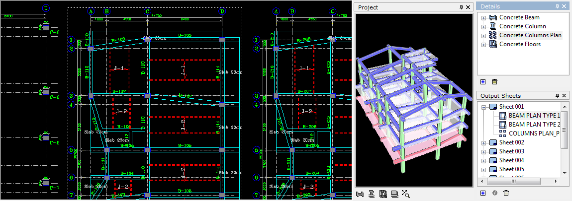
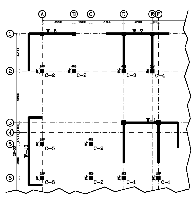
For viewing the Columns Plan of structure, it is only needed to double click on item with the name of "Concrete Columns Plan" in Details window. A sample of concrete columns plan is shown in following figure.
2. Beams Plan of Concrete Building
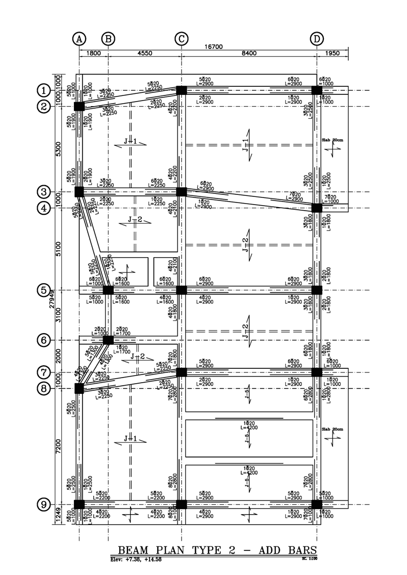
For viewing the Beams Plan for different stories of structure, it is only needed to double click on item with the name of "Concrete Floors" in Details window. Then the Beams Plan list which was generated by Omid Negar, will be shown. By double clicking on name of each beam plan, it will be shown. A sample of concrete beams plan is shown in following figure.
Please be noted that, according to similarity between beams, automatically or based on user's decision (which was explained in Quick Start Guide), the Beams will be classified. Then based on defined classifications, the beams plans will be presented.
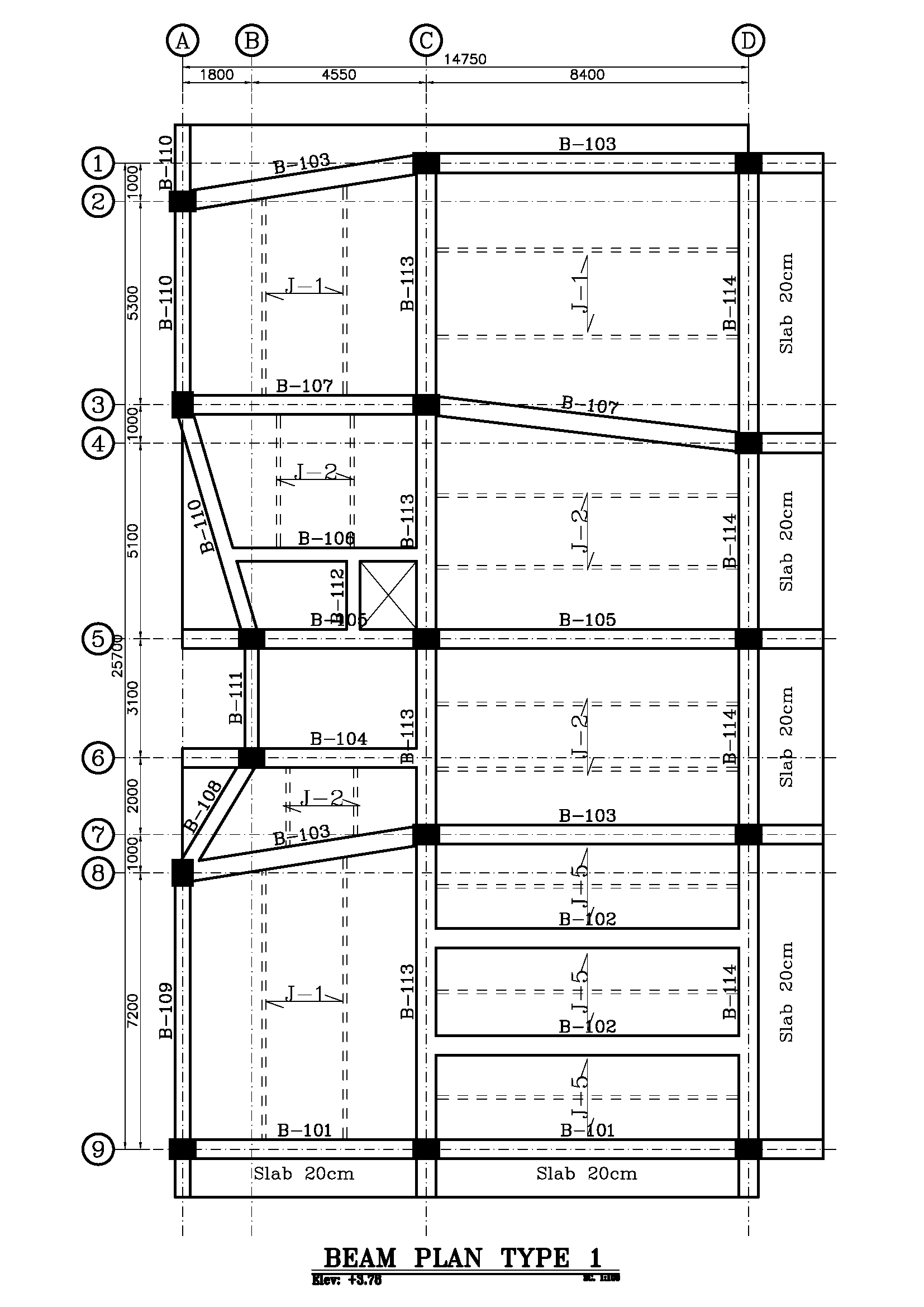
The Omid Negar, has the ability to draw "Add-Bars Plan" and "Stirrups Plan". The "Add-Bars Plan" and "Stirrups Plan" are subcategory of related Floor Plan.
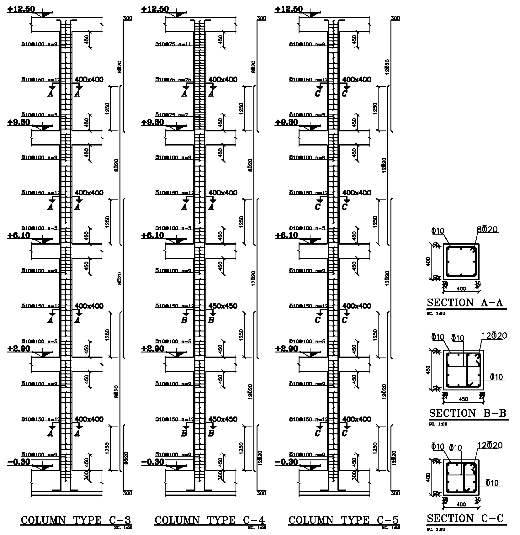
3. Concrete Column's Structural Details
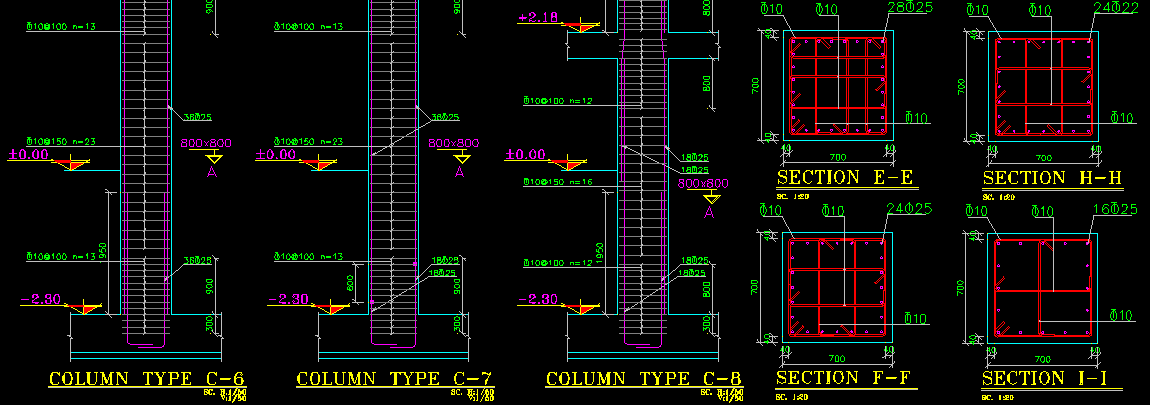
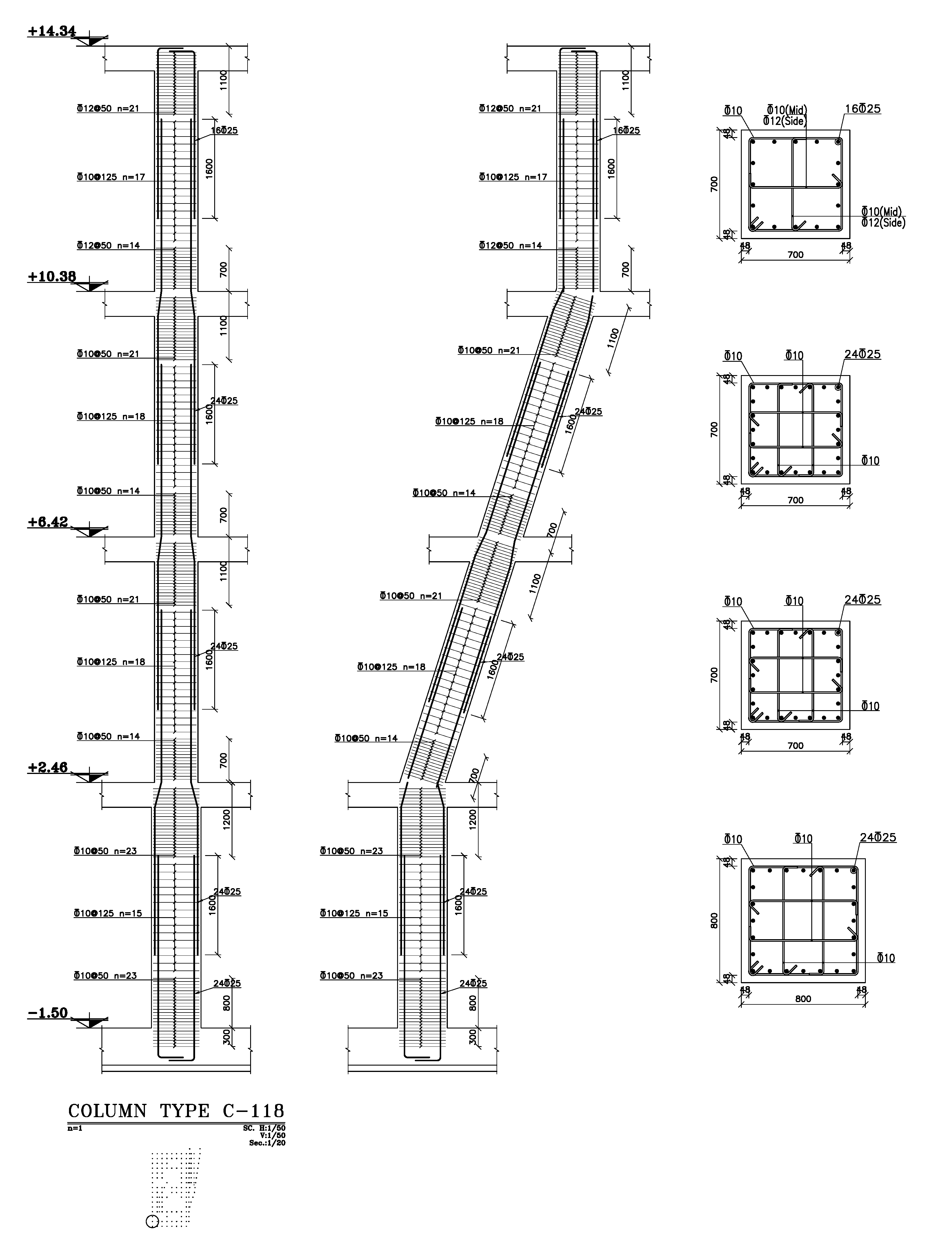
For viewing the details of each type of Column, it is only needed to double click on item with the name of "Concrete Columns" in Details window. Then list of column types which was generated by Omid Negar, will be shown. By double clicking on name of each column type, the elevation and sections list of it will be shown. By double-clicking on name of "Elevation", the elevation view of column type will be shown. And by double-clicking on each section name, the section of column will be shown. Omid Negar automatically will generate a section for each column type at each story. A sample of concrete column details is shown in following figure.
Please be noted that, according to similarity between column types, automatically or based on user's decision (which was explained in Quick Start Guide), the Column Types will be classified. Then based on defined classifications, the Columns Plan will be presented.
Note 1: Name of Column Sections at Details window, will be generated separately for each column type. But when the user wants to generate the structural drawings and make and arrange the output sheets (In Output Sheets window), the program will globally name all sections for all different Column Types sequentially and without repeating. Whilst at this step, if two different sections of different column types be similar, Omid Negar considers one section.
Note 2: The program can recognize the inclined columns and draws the details based on given data from model's output.
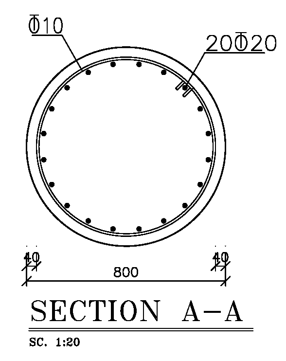
Note 3: The program can also generate drawings with circular concrete columns. Viewing of structural details for this kind of column is exactly same as other columns which was described earlier. Of course the bar bending criteria for circular columns are specially considered by Omid Negar for these type of columns. A sample section detail of a circular concrete column is presented at following figure:
4. Concrete Beam's Structural Details
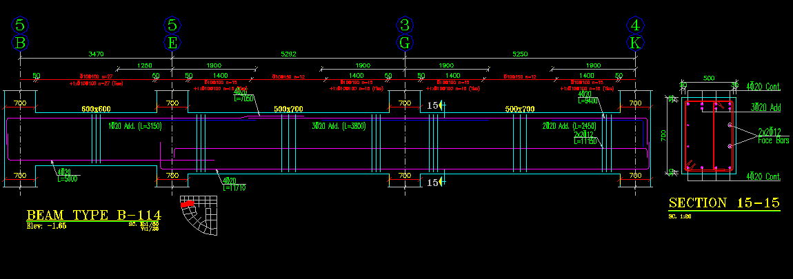
For each type of concrete beam which is shown in beams plan, the program will draw an elevation view of it. For viewing the details of each type of Beam, it is only needed to double click on item with the name of "Concrete Beams" in Details window. Then a list of beam types which was generated by Omid Negar, will be shown. For separating beam type related to each story, the first digit of beam type's names shows the story number which the beam type is located in. For example the beam type name of B-203 is located in second story.
Note: If based on design considerations (Which is described in user's manual), the program classifies two different beams located in two different stories as one beam type, naming will be done according to the lower story.
By double clicking on name of each beam type, the elevation and sections list of it will be shown. By double-clicking on name of "Elevation", the elevation view of beam type will be shown. And by double-clicking on each section name, the section of beam will be shown. Based on user's request, the program can generate more sections at arbitrary locations. This can be done by clicking on the "Edit Detail" in "Edit" menu.
For example, in following figure, for beam type B-222 the elevation view is shown. As it can be seen, all required details like continuance and additional bars, stirrups at different parts of beam, naming of columns axis, dimension of beams and other information is presented by Omid Negar automatically based on drawing standards. Diameter, distance and length of rebars, beam dimension on each span, columns dimensions are drawn based on the selected scales. Considering the scale, each difference between spans, will be shown in details. The suitable locations for splicing or bending the continuance rebars will be selected and optimized by Omid Negar and all related data will be presented in detail drawings.

Note: The program can recognize the inclined concrete beams based on the model and can draw details of it precisely. As it is shown in following figure, the inclined concrete beam in an sloped roof will be generated by Omid Negar exactly based on definitions in ETABS model, considering all data of longitudinal and lateral reinforcements, beam dimensions, attached columns dimensions and locations. Drawing of sections are exactly as same as the horizontal beams, and simply can be drawn as described before.

5. Concrete Shear Wall's Structural Details
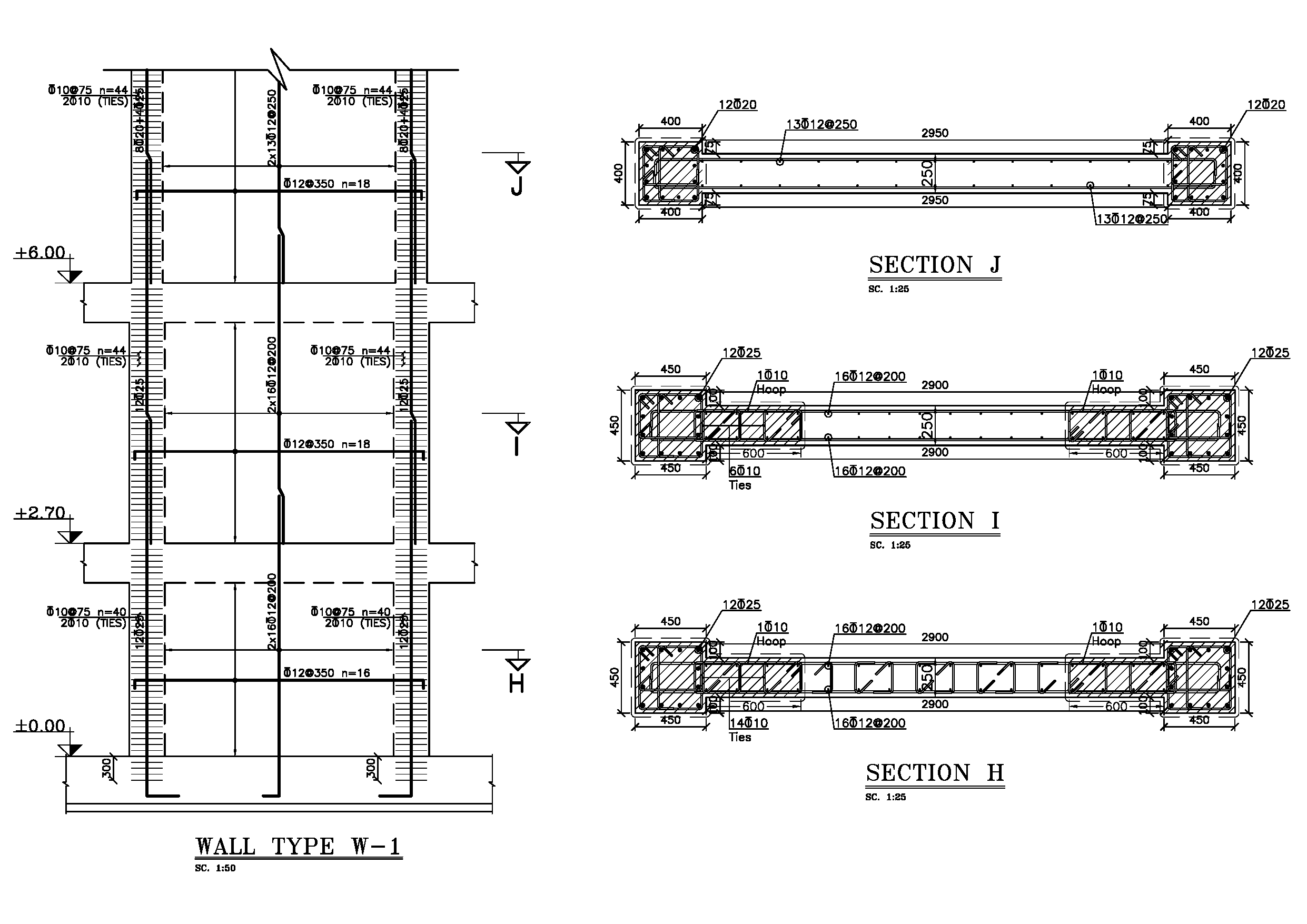
For each wall, there is a type defined. Each wall type has one elevation view and sections. Number of sections is equal to define stories for that wall type.
For viewing the wall's elevation and section details, select "Concrete Wall" in details window. All wall types is shown in order.
If you need to edit and modify the wall which is generated using ETABS model, after selecting the wall type in Details window, press Ctrl+D, or click on button in bottom of Details window.
B. Viewing Output Sheets: Output Sheets Window
For generating final sheets of drawings which are known as the final output of program, it is enough to transfer each generated detail which is described in Details window to Output Sheets window with the simple Drag & Drop method. Then the program will arrange the selected details in output sheets automatically. It is possible to relocate or change these details manually.
Instead of manually Drag & Drop the details in output sheets, the other method for generating all of the structural output sheets, is to automatically arrange all sheets together and sequentially using the Arrange Output Sheets command which is located in the Project menu. There is two options available for auto-arranging. The first option is to arrange based on Object Type. For example foundation details in one sheet, columns in other sheet and also beams to be in separated sheets. The second option is to arrange by story, is as similar as the first option plus the beams related to each beams plan will be placed with the related beams plan together in the same output sheet. This will make the construction easier.

